


- 音箱技术 Publish Date:2015-06-17
-
Proper Signal (Time) Alignment—Getting Loudspeaker Drivers In Sync
Since the early 1980s, the term “time alignment” has been tossed around pretty freely, and with dubious degrees of accuracy.
Note, however, that this was far from the first time the concept was noticed. Indeed, the engineers who provided the loudspeakers for the first “talkie” film, Al Jolson’s The Jazz Singer, noticed that the “taps” of the tap dancing scenes came out of the high-frequency (HF) horn and folded-horn low-frequency (LF) woofer at different times.
Ever since, designers have been trying to time-align loudspeakers. The phrases “time align,” “time aligned,” and “time alignment” are trademarks of E. M. Long, the inventor of the famous UREI 813 monitor loudspeaker used in recording studios. Thus for purposes of this discussion, we’ll use generic term “signal alignment” to avoid having to use those ?’s and ?’s.
Most folks believe that signal alignment between drivers in a loudspeaker cabinet is a matter of measuring the difference in distance to the front of the cabinet from each of the driver’s voice coils. Then, by adding delay to the driver closest to the cabinet ? delay that corresponds to the difference ? the signal of all drivers will then be aligned properly.
However, this is not correct! We must understand both filters and phase to properly signal-align HF and LF drivers.
All filters “rotate” phase, causing a positive “phase-shift” to the frequencies that pass through them. Because 360 degrees of phase-shift equals one wavelength, and wavelength can be described in terms of distance or time, any phase-shift at a given frequency can be described as a signal delay of an exact length of time.
For example, because 1000 Hz is 1000 cycles per second, one wavelength (or cycle) is 1/1000th of a second, or 1 millisecond (ms). Therefore, 360 degrees of phase-shift at 1 kHz is 1 ms of delay. Then 180 degrees of phase-shift (1/2 wavelength) is 0.5 ms of delay and 90 degrees (1/4 wavelength) is 0.25 ms of delay at 1 kHz. For 2 kHz, because the wavelength of a cycle is one-half as long, then the phase-shift delays would all be one-half the time of delay. At 20 Hz, 180 degrees of phase-shift (1/2 wavelength) is 25 ms, or 28.25 feet of delay at the speed of sound.
Getting To The Point
Where am I going with this? All crossover and equalization filters are electronic filters that impart phase shift/delay to any signal passing through them. Likewise, all loudspeakers are acoustic filters that also impart signal delay.
So in order to signal-align a woofer and horn driver (or tweeter), we must offset not only the physical difference in distance from the drivers to the cabinet front, but we must also offset the filter phase-shift delay of the crossover, the post-crossover equalization filters exclusive to each driver, and the loudspeakers as acoustic filters. Pre-crossover equalization filters are not considered because they impart the same delay to both drivers.
So let’s put all this newfound knowledge to work and signal-align a two-way loudspeaker system comprised of a 12-inch woofer (LF section) and a 90-degree by 40-degree horn/compression driver (HF section).
Before beginning, however, make sure that both drivers are in absolute polarity, or at least in relative polarity to each other. This can be done by checking the wiring, or using a polarity checker without any EQ or crossover filtering on either driver, or by checking the impulse response for a first positive swing with a measurement system.
Figure 1 shows the individual frequency responses of both the LF and HF sections with the measurement mic directly on-axis, halfway between the drivers’ centers at a distance five times the woofer’s diameter. Note that I have equalized each section flat, past the intended crossover frequency, before adding 24 dB/octave (4-pole) Linkwitz-Riley (L-R) crossover filters.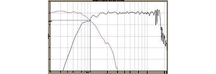
Figure 1: Individual LF & HF frequency responses with 24dB/octave L-R crossover filters at 1 kHz. (click to enlarge)I find that equalizing the drivers first, using post-crossover filters exclusive to each driver, provides the smoothest frequency response through the crossover region once their responses are combined. It also enables the crossover filters to combine much closer to their theoretical ideal.
Also note that where the response curves intersect is the acoustical crossover frequency and, for signal alignment, this point should be 6 dB down for a 4-pole filter. To get this, one must make sure the levels of each driver are the same and then play with the electronic crossover frequencies until the acoustic results are what is desired.
In this case, I wanted a 1 kHz crossover, and to get it, both drivers ended up with a 950 Hz electronic crossover. Remember, the electronic cross-over frequency is in series with, and modified by, the EQ filters and acoustic filters (read loudspeakers) that produce the acoustic result that really counts.
Going Further
Figure 2 shows the combined response of both drivers superimposed over the individual responses. Note the cancellation at crossover with a slight addition at 600 Hz. The 11 dB dip indicates the need for signal alignment of these drivers because they are reproducing the same frequency out-of-phase, and thus cancel each other’s output. Equalization cannot fix this because it will affect both drivers equally and the cancellation will still occur.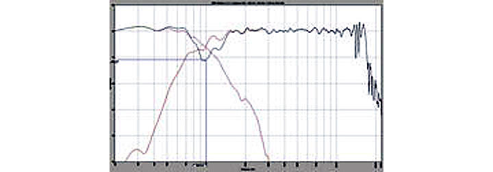
Figure 2: Combined response of both drivers with an 11 dB dip at the crossover frequency. (click to enlarge)Figure 3 adds the phase curve of the combined response. Note the abrupt change in the slope of the phase curve at the crossover. This also indicates the driver misalignment that causes the dip in the response.
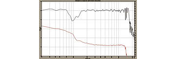
Figure 3: Combined response of both drivers with the phase curve showing an abrupt slope change at the crossover misalignment. (click to enlarge)At this point, most who perform signal alignment would simply begin adding delay to the closest driver and watching the phase curve until its slope would be as straight (straight ? not flat) as possible. If you only have an RTA and can’t measure phase, then you’re out of luck. This can also be a rather tedious task because the last several delay steps to either side of optimum alignment can look almost the same.
This might not matter from a frequency-response point of view, but this alignment also determines the aiming of the on-axis lobe at the crossover frequency. To get the lobe exactly perpendicular to the cabinet face, it’s best to attain the best alignment setting at the measurement microphone position.
The easiest method to find this exact alignment setting can also be employed by an RTA (real-time analyzer).
Reverse the polarity of the HF driver (polarity, not phase). Then start increasing the delay to the closest driver ?-in this case, it’s the woofer.
Look for the maximum cancellation at crossover. Unlike the straight phase slope method, it will be very easy to determine the delay step with the maximum null. It will be a 30 to 40 dB deep dip. The dip, even one step under or over the optimum delay, will be smaller by several dB.
Getting Lucky
Figure 4 compares the combined response with the HF, both in and out of polarity. Just by luck, the reversed-polarity response looks very flat.
One might be tempted to stop here and use the system as is. And before the advent of DSP (digital signal processing), that is exactly what was often done. Passive crossover networks internal to loudspeaker systems are often 12 dB/octave (2-pole) crossovers.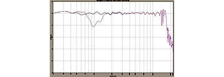
Figure 4: Combined response with both drivers in polarity (dip) compared to combined response with HF driver in reversed polarity (flat).(click to enlarge)A 2-pole crossover produces a 3 dB roll-off at crossover and the drivers are 180 degrees apart in phase. Reversing the polarity of the HF section puts them in phase with a 3 dB bump at crossover. Many loudspeakers with passive crossovers are designed this way.
The important question at this point: can you hear the difference between absolute polarity and reversed polarity signals? The short answer is that if the signal is a very asymmetric waveform, you can, and if it’s a very symmetric waveform, you can’t.
So unless you listen to nothing but flute solos, you’ll want to take advantage of modern DSP capability to provide optimized crossovers with both drivers in proper polarity. Note that Figure 5 shows the slope of the phase of the reversed HF combined response breaking subtly at the crossover frequency, indicating some misalignment.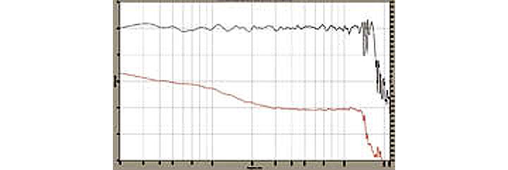
Figure 5: Combined response with HF polarity reversed. Note the slight break of the phase curve slope at crossover. (click to enlarge)Figure 6 graphically illustrates the process of finding the null at crossover with the HF driver polarity reversed. The dip at crossover is 37 dB deep at the optimum LF delay of 0.417 ms. Note that it is 10 dB deeper than the next closest delay step of 0.396 ms.
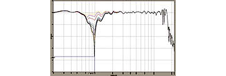
Figure 6: Finding the deepest null with the HF driver polarity reversed. (click to enlarge)Figure 7 depicts the phase curve of the deepest null. It’s a perfectly vertical line, indicative of being right at 180 degrees out-of-phase.
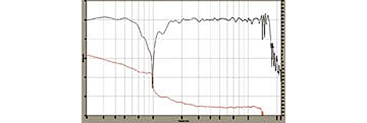
Figure 7: The phase slope of the deepest cancellation null is a perfectly vertical line, indicating exactly 180 degrees out-of-phase. (click to enlarge)Once you’ve found the delay step that produces the deepest null with the HF driver polarity reversed, simply put the HF driver back in proper polarity. Your system is now in proper signal alignment.
Figure 8 is the final result. Compared to the reversed HF response of Figure 5, the phase curve slope is straighter through the crossover region and there is also no slight HF cancellation dip in the woofer’s response around 600 Hz either.
Figure 8: Final signal alignment with HF in proper polarity. (click to enlarge)If you have a measurement system that measures phase, be sure to confirm that the final resulting phase slope is a straight line. This ensures not being one cycle off in either direction by delaying the wrong driver, or by delaying the right driver 360 degrees too much, or too little at short wavelength crossover frequencies. The frequency response results could look the same. One should be particularly careful about this if using an RTA with no phase measurement capability for confirmation.
And by all means, have fun!
John Murray is a 35-plus-year pro audio industry veteran, working for EV, MediaMatrix and TOA. He has presented two AES papers, chaired three SynAudCon workshops and is a member of the TEF Advisory Committee and ICIA adjunct faculty.Back

